English
 简体中文
简体中文
POFI EDM TOOLING SYSTEM CO.,LTD
+86-0769 85071992
E-mail:info@pofi-workholding.com
- All
- Product Name
- Product Keyword
- Product Model
- Product Summary
- Product Description
- Multi Field Search
Views: 20 Author: Site Editor Publish Time: 2023-08-21 Origin: Site
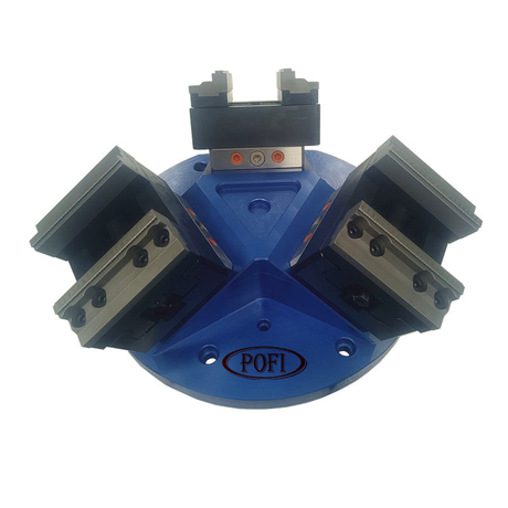
ER-008856 Swing Rotary Vice 0-100
1. Introduction

A. Swinging vice body
B.E. Angle adjusting bolt (brass block is Angle adjusting wedge)
C. Chip mounting holes
D. Pull nails
F. Stop block mounting holes
G. Clamp claws
H. Locking bolt
1.360° rotation of clamping head
2. The maximum load is 5 Kg, and the maximum Angle adjustment of the two axes is +0.25°
3. Use and maintenance, can be used according to the diagram
Loosen the Angle adjusting bolts B and E first, clamp the workpiece: loosen the locking bolt H, and rotate the workpiece clamp Tighten the head to the required Angle position, and then lock the bolt H. Trace on workpiece position Scew to adjust. When adjusting bolt B(or E) in one direction, the adjusting bolt in the opposite direction must be loosened at any time. The maximum locking force acting on the gripper G when clamping the workpiece is 6Nm.

Note:
All adjustment diaplooms must be relaxed after use to restore the diapladyphone normality!!
Do not loosen or re-lock the positioning support foot screws at will!!
After maintenance, please keep the vice positioning support out and the positioning square hole clean, and check the positioning at any time Support the flatness of the foot and locate the square hole orifice to ensure the wear of the tiger Clamp acquisition Accurate support and precise positioning. And keep the overall cleanliness of this product. The use of fixture can not only reduce the clamping calibration time, but also improve efficiency. Please be careful not to exert too much force when using, clean up in time after processing, put neatly.